
AHT20 thermometer driver
I wrote a new driver for the AHT20 temperature and humidity
sensor in
Rust. This is a continuation of my Barometer
build article, where I
re-use the
lps25_pressure_sensor_demo
project to add a temperature sensor on the with_aht20_sensor branch.
I’m a complete novice at Rust and embedded programming. These projects are my attempts to learn more about both while having fun and making something useful.
You can find the driver at:
If you have an I2C device and delay configured, this is how you use the driver:
let mut aht20_uninit = aht20_driver::AHT20::new(
    i2c, aht20_driver::SENSOR_ADDRESS
);
let mut aht20 = aht20_uninit.init(&mut delay).unwrap();

let aht20_measurement = aht20.measure(&mut delay).unwrap();
rprintln!("temperature: {:.2}C", aht20_measurement.temperature);
rprintln!("humidity: {:.2}%", aht20_measurement.humidity);
You can see it used in the included example or in my lps_25_pressure_sensor_demo branch.
Motivation
There already is a driver for this sensor called aht20, and it’s written by Ferdia McKeogh. I’m sure it’s very good, so you might ask: why write another one? There are two reasons.
The first reason is that the driver takes ownership of the embedded-hal delay, which means it can’t be used in combination with other things that also need a delay. In my barometer build, the delay is used to pause between readings, and to control the HD44780 LCD panel. More on this issue in the “The issue with delay” section.
The second is that the driver is licensed under the AGPL 3.0, and while I’m a big fan of copyleft licenses the AGPL is, in my opinion, not suitable for a library since it has no linking exception like the LGPL.
Moreover - it was great fun to write, and ever since doing the CO2 Sensor Knurling Session, I’ve been hoping to find a reason to write a driver myself to practice what I learned there. Now I had both a sensor and an excuse. The Knurling Sessions are really good fun, and if you want a friendly and fun way to learn some Rust and embedded programming, I recommend them!
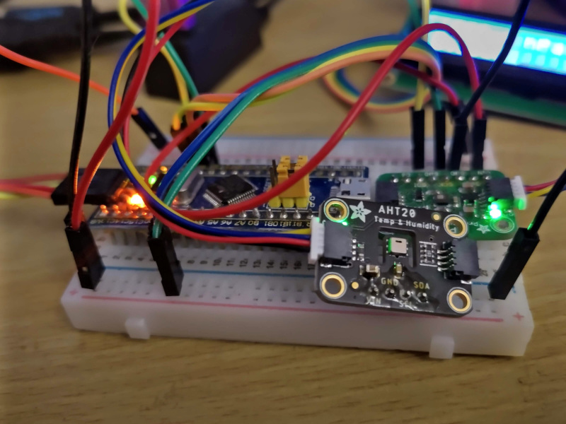
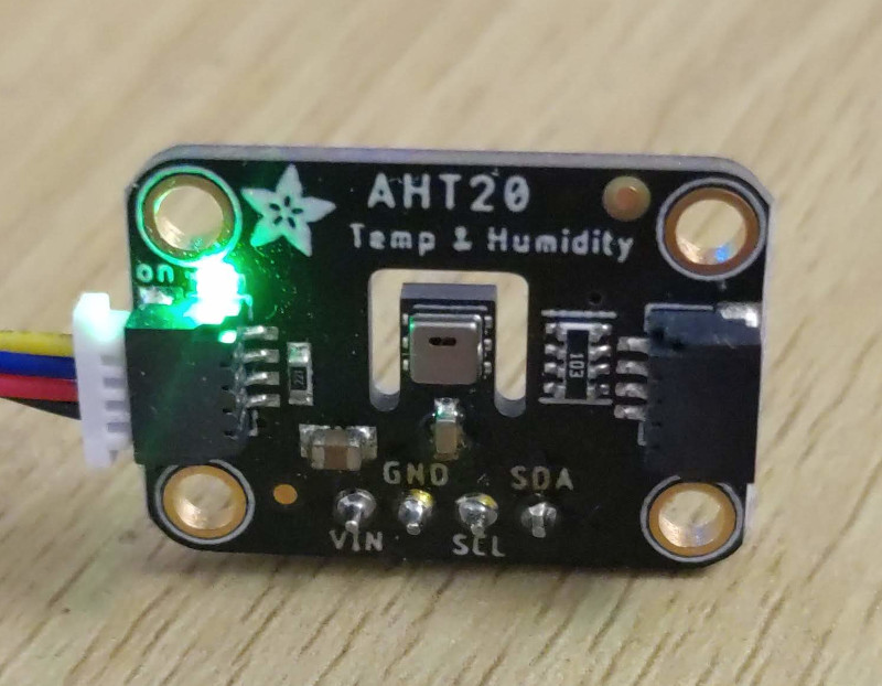
The Sensor
The AHT20 by Aosong is a temperature and humidity sensor. I’ve been using it via the Adafruit AHT20 - Temperature & Humidity Sensor Breakout Board - STEMMA QT / Qwiic (Product ID 4566).
I’ve got a number of sensors that can give me a temperature reading right here on the desk as part of dev boards and other sensors. Their current temperature readings will hopefully demonstrate why I feel I need a dedicated sensor.
- Sensiron SCD30 CO2 sensor: 23.9°C
- nRF52840 DK development kit: 25.0°C
- LPS25H barometer: 16.78°C
There is an 8.2°C difference between the barometer and dev board readings. None of those sensors are even within two degrees of the correct temperature.
The temperature as measured by the AHT20 is a much more plausible 21.4°C. I want to be able to trust the sensor, and the AHT20 is one I think I can trust.
The Adafruit breakout board comes with Stemma QT connectors and they’re really convenient. Having used them, I’m now convinced that I should have used the connector for the LPS25 as well. They’re great to work with, easy to connect, hard to get wrong, and more robust than the jumper wires on the breadboard which glitch the I2C connection for me when they’re touched.
The Stemma QT connector is the same as the Sparkfun qwiic connector, which is great as it means there’s a larger ecosystem of things to connect with them.
How does the sensor work?
The first step to writing a driver is to learn how the sensor works. I had previously followed the Knurling Session, which made a driver for the SCD30, so I had a pattern to follow. From that I knew that I should find and read the data sheet for the device.
The data sheet
That leads us to the first hurdle - the datasheet on the manufacturer’s website is version 1.0, and it’s much less helpful than version 1.1 which is stored on Adafruit’s CDN. I got lucky having read the Adafruit guide and clicked the download datasheet link there and noticing the version difference.
The parts we need are on page 8 and 9 of the data sheet - sections 5.3 through to 6.2. Trying to make sense of this data sheet is like solving a cryptic puzzle. It’s word salad in places. Some examples of confusing things:
- The “initialization” and “trigger measurement” commands both have a definition of “Keep main engine”. What does that even mean? The names are self-explanatory though, so this isn’t a blocker.
- The Basic Commands table doesn’t include the “check status” command which is essential to initializing and reading from the device.
- The same Basic Commands table doesn’t include the parameters that the commands need. They’re only mentioned in the sensor reading process section, and no explanations are given for the parameters at all. As far as I can tell, the commands with parameters should just be treated as three-byte commands.
- The CRC check explanation made no sense to me at all. There’s a section in this post about that later. I could just have skipped the CRC check, but I wanted to try to get this right.
- The process for waiting for data from the sensor involves the “check status” command, but you can also directly read a state byte from the bus when data is ready - and it’s really not clear how these two status systems interact, or what happens if you abandon the read after the status byte. I had to just try it and see.
- The datasheet mentions both a 75ms and an 80ms wait before reading data after issuing a “trigger measurement” command. Which is right?
- Section 5.5.5 “Calculate the temperature and humidity values.” doesn’t explain that at all. More on this below.
Device flow chart
After reading through the data sheet a lot - I created the following flowchart which worked for me as I implemented the driver. This does not include the “soft reset” workflow, but that is mostly trivial - you send the “soft reset” command, wait 20ms, then you’re able to issue “trigger measurement” again. I’m not sure when you’d need to do a “soft reset”, but I implemented it.
          Start (Power on)
                 │
                 ▼
             Wait 40 ms
                 │
                 ▼
  Command::CheckStatus (0x71)   ◄───    Wait 10 ms
                 │                           ▲
                 ▼                           │
         Status::Calibrated ──► No ──► Command::Initialize (0xBE)
                 │
                 ▼
                Yes
                 │
                 ▼
Command::TriggerMeasurement (0xAC)   ◄─┐
                 │                     │
                 ▼                     │
            Wait 80 ms                 │
                 │                     │
                 ▼                     │
  Command::CheckStatus (0x71) ◄──┐     │
                 │               │     │
                 ▼               │     │
            Status::Busy  ───►  Yes    │
                 │                     │
                 ▼                     │
                No                     │
                 │                     │
                 ▼                     │
            Read 7 bytes               │
                 │                     │
                 ▼                     │
            Calculate CRC              │
                 │                     │
                 ▼                     │
              CRC good ─► No  ─────────┘
                 │                     ▲
                 ▼                     │
                Yes                    │
                 │                     │
                 ▼                     │
    CRC-checked Status::Busy ─► Yes ───┘
                 │
                 ▼
                No
                 │
                 ▼
       Calc Humidity and Temp
(Made with asciiflow.com)
Getting a sensor reading
The first step to writing some code is deciding where to start.
The data sheet (section 5.4.4) says we get to read 7 bytes from the sensor, and the 7th byte is CRC data. I felt this was a good place to start, as it is an independent bit of code I could tackle first.
The CRC check
A CRC check is a way to do error detection. Knowing it’s a CRC check is good, but the data sheet cryptically informs us:
CRC initial value is 0xFF, crc8 check polynomial CRC[7:0]=1+x**4 + x**5 + x**8
Those are certainly some words. How do we select the right parameters for a call into the CRC Any crate which I decided to use to perform the CRC calculations? The CRC Any docs show there’s a lot of different variations of CRC8, and we need to know the exact one to select.
If we do what I did, and go look at the Wikipedia page for Cyclic redundancy check, we find that there are 9 different ones in the CRC8 family. But, which one is it?
Comparing the polynomials, we see that it uniquely identfies
“CRC-8-Dallas/Maxim” as the particular CRC variant. The “Normal” for this
variant is 0x31, which turns out to be important to know. I explore what this
magic value is just below.
Looking at the CRC Any docs
we find a tempting looking crc8maxim function, but sadly the “init value” does
not match the value we were given. We can create our own CRC variant with the
create_crc
method. It looks like this:
// Poly (0x31), bits (8), initial (0xff), final_xor (0x00), reflect (false).
let mut crc = CRCu8::create_crc(0x31, 8, 0xff, 0x00, false);
That solves our practical problem. But, that magic value of 0x31, what is it?
The 7.2 Representation of generator
polynomials
section of Understanding and implementing CRC (Cyclic Redundancy Check)
calculation
by Bastian Molkenthin explains how to go from
CRC[7:0]=1 + x**4 + x**5 + x**8 to 0x31 as the hex representation.
The **N is the Nth bit (from the right, zero indexed). Also:
The most significant bit [(x**8)] is left out in the hexadecimal representation
If we drop that - the expression is now 1 + x**4 + x**5. In this x**4 and x**5
represent 1s in a byte in positions 4 and 5 (0-indexed) - and then we add 1. This
gives us a this byte: 0b0011_0001.
Checking what that looks like in hex:
>>> hex(0b0011_0001)
'0x31'
We see that it’s the same as the “Normal” value we got from wikipedia, which confirms it’s right. It’s also what the Knurling’s test driver crate uses, and indicates this is either a value and CRC type specified by I2C, or a common sensor selection.
Having gone and implemented the CRC check of course doesn’t mean I used it correctly. At first I only applied the CRC check to the numerical data returned by the sensor for temperature and humidity, but leaving out a state byte it also sends. After fixing that however, all was good with the CRC check.
The CRC Any crate is excellent, and it did all the heavy lifting in the code, all I had to do was to figure out what the CRC parameters were supposed to be. If the data sheet had been better, this would have been very easy.
The code is very easy to understand once you get past the magic values.
fn compute_crc(bytes: &[u8]) -> u8 {
    // Poly (0x31), bits (8), initial (0xff), final_xor (0x00), reflect (false).
    let mut crc = CRCu8::create_crc(0x31, 8, 0xff, 0x00, false);
    crc.digest(bytes);
    crc.get_crc()
}
Getting some sensor values
If we follow the flowchart above, and we’ve initialized the device, issued the “check status” command, and waited just right - we’ll be able to read 7 bytes of sensor data, and now we need to interpret this data.
We’ve already covered the CRC byte at the end. The status byte at the start is a repeat of the “check status” we just did. We verify the sensor is still reporting ready to be diligent.
That leaves the five bytes in the middle, from which we can extract the temperature and humidity. This image from the data sheet is all the help we get:
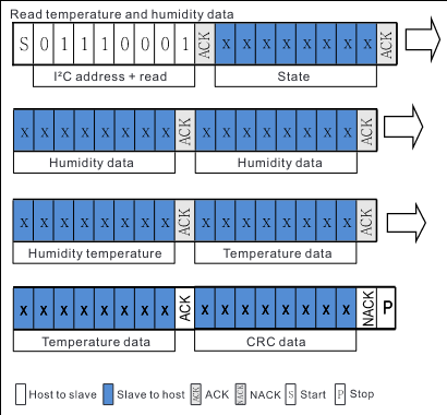
Along with two signal transformations:
RH[%] = (Srh / 2**20) * 100%
and
T(C)=(St / 2**20) * 200 - 50
Note how in the screenshot from the data sheet the bytes are labeled as [“Humidity data”, “Humidity data”, “Humidity temperature”, “Temperature data”, “Temperature data”], which made me assume a 16-bit value for humidity, an 8 bit value for “humidity temperature” (whatever that was) and 16 bits for temperature.
let humidity_bytes: &[u8] = &sensor_data[..2];
let humidity_temperature_byte: u8 = sensor_data[2];
let temperature_bytes: &[u8] = &sensor_data[3..5];
This is completely wrong - especially the humidity_temperature_byte. There is
no such thing as “humidity temperature”.
The data turns out to be given as two 20-bit values which you read as five bytes. There is absolutely no explanation for how to extract the data - this took me a long time and a lot of poking aimlessly at it in the Python interactive console to figure out. I got a lot of nonsense results until I realised the instruction to divide by 2**20 was a clue about 20 bits in addition to an actual value to divide by. Two bytes (16 bits) plus a half byte (a nibble)!
Why the Python interactive console? Well, I also had some trouble wrapping my head around f32::from_be_bytes, from_bits etc, and Python was a really quick way to iterate on that same data. I’ll get back to the f32 docs… some other time.
I left myself quite an essay in the code. I doubt I’ll forget how to do this, but better safe than sorry. I wish the data sheet had just said “20-bits” somewhere, and saved me a lot of head-scratching.
If you’re interested in more details, you can take a look at the SensorReading::from_bytes method.
Writing an embedded HAL driver
When writing a driver, I of course needed to learn how one is supposed to write an embedded HAL driver. I followed along the Knurling Sessions, which does implement an I2C sensor driver, but I wasn’t sure if perhaps that was simplified to make a more compelling tutorial. I started reading the embedded-HAL docs.
A diversion to the nb crate
The docs almost immediately say:
These traits make use of the nb crate (please go read that crate documentation before continuing) to abstract over the asynchronous model and to also provide a blocking operation mode.
Off I go to read the nb crate docs. The
embedded HAL docs refer to try_nb! and other macros which don’t seem to exist
any more (I think they did in version 0.1.0). I keep reading.
I spent a bunch of time trying to understand how the nb crate should be used
so that my driver can wait during initialization or reads, but I failed to
really understand. However, I also noticed that at least for the stm32f1xx-hal
i2c
implementation I’m using, there only seems to be a blocking I2C implementation,
so therefore I don’t need to use the nb crate’s asynchronous model.
I still don’t fully understand the nb crate. I understand what its purpose
is, but I don’t think I could apply it in this driver without quite a bit of
further reading. I’ve left it like that for now, and focused on implementing
the driver using the blocking I2C support.
Speaking I2C, issuing commands
The great news is that the embedded HAL implementation makes it really easy to talk to I2C devices. Here’s how I ask for a status byte from the sensor by sending the “check status” command, then reading a byte back containing the answer:
pub const SENSOR_ADDRESS: u8 = 0b0011_1000; // This is I2C address 0x38;

pub enum Command {
    CheckStatus = 0b0111_0001, // 0x71
    // other commands, ...
}

// In the AHT20 struct impl:
pub fn check_status(&mut self) -> Result<SensorStatus, Error<E>> {
    let command: [u8; 1] = [Command::CheckStatus as u8];
    let mut read_buffer = [0u8; 1];

    self.i2c.write(SENSOR_ADDRESS, &command).map_err(Error::I2c)?;
    self.i2c
        .read(self.address, &mut read_buffer)
        .map_err(Error::I2c)?;

    Ok(SensorStatus::new(read_buffer[0]))
}
That reads the sensor response byte into a SensorStatus struct. We use that to check if the sensor is calibrated, or if the sensor is busy generating a reading and we should wait for it.
pub enum Status {
    // Status bit for busy - 8th bit enabled. 1<<7, 0x80
    Busy = 0b1000_0000,
    // Status bit for calibrated - 4th bit enabled. 1<<4, 0x08.
    Calibrated = 0b0000_1000,
}

#[derive(Debug, Clone, Copy)]
pub struct SensorStatus(pub u8);

impl SensorStatus {
    ...
    pub fn is_calibrated(self) -> bool {
        (self.0 & Status::Calibrated as u8) != 0
    }
}
Even the AHT20Initialized::measure_once method is actually very easy to understand, which I think is an endorsement of the embedded-HAL ecosystem.
The issue with delay
I’m only a budding rustacean (a larva?), and it’s very possible I’m unaware of some way to deal with this. But, the embedded HAL blocking delay implementation has the surprising behavior of having functions that requires the delay to be mutable.
delay is mutable because the delay methods take a &mut self parameter. The
previously existing aht20 driver’s
Aht20 struct takes
ownership of the delay - and therefore is the only thing that can use the
delay. This of course is a problem if I’d like to use a second driver which
needs a delay, or want to use the delay in my own code (which I do).
This is the primary reason why I’ve written this driver for the Aht20. It also explains why the hd44780-driver that I use in my barometer build crate takes the delay as a parameter to its functions like this:
lcd.write_str("Hello, world!", &mut delay);
rather than referencing the delay as part of its driver struct.
In that driver’s github issues you can see this exact issue crop up: Issue #16, “HD44780 takes ownership of Delay, and PR #15 changes the behavior to what it is now.
Both the stm32f1xx (blue pill) that I’m using in the barometer build, and the nrf52840 that I’m using in my CO2 sensor project have a delay that requires being borrowed mutably. I don’t know if any other implementations are different, but these certainly can not be shared between drivers if a driver owns it.
In fact, my first instinct was also to create my driver struct this way:
/// An AHT20 sensor on the I2C bus `I`, with a Delay device `D`.
pub struct AHT20<'a, I, D>
where
    I: i2c::Read + i2c::Write,
    D: DelayUs<u16> + DelayMs<u16>,
{
    i2c: I,
    address: u8,
    delay: &'a mut D,
    initialized: bool,
}
But of course here you can see the exact problem - with delay being a mutable reference. Nobody else would be able to use this delay, and it can not be cloned. So if I had done this - I wouldn’t be able to also use the LCD panel, or other drivers that requires a delay.
I was a little disappointed as that was my first use of an explicit lifetime,
and the functions all taking &mut delay look a bit inelegant. Instead, the
driver struct is the much simpler:
/// An AHT20 sensor on the I2C bus `I`.
pub struct AHT20<I>
where
    I: i2c::Read + i2c::Write,
{
    i2c: I,
    address: u8,
}
the function that requires a delay looks like:
pub fn init(&mut self, delay: &mut (impl DelayUs<u16> + DelayMs<u16>)) -> Result<AHT20Initialized<I>, Error<E>> {
    ...
}
Writing tests
I wrote tests as I was creating this driver, and it helped me think about the implementation immensely. Testing in Rust is a joy. If you don’t find it a joy I am not responsible, and you may be dead inside.
Ferrous System’s Testing a driver crate is a wonderful article, and I highly recommend reading it if you’re interested in writing tests for a driver.
Unit testing made development much easier, as did writing a test application for it along with the driver. Having an application use the driver immediately meant I was able to ensure my assumptions were correct (or entirely wrong - as was the case on a few occasions).
I used embedded-hal-mock by Danilo Bargen heavily in the tests. It’s lovely, especially the I2C mocking. Using it is really easy, and the error messages are clear and obvious.
The Knurling test embedded app example repo which goes along with the blog post was very useful, and a bunch of the code examples were lifted straight into this driver. Thank you Knurling!
Here is one of my tests:
/// Test sending the CheckStatus I2C command, and read a status byte back.
#[test]
fn check_status() {
    let expectations = vec![
        Transaction::write(SENSOR_ADDRESS, vec![super::Command::CheckStatus as u8]),
        // 4th bit being 1 signifies the sensor being calibrated.
        Transaction::read(SENSOR_ADDRESS, vec![0b0000_1000]),
    ];
    let mock_i2c = I2cMock::new(&expectations);

    let mut aht20 = AHT20::new(mock_i2c, SENSOR_ADDRESS);
    let status = aht20.check_status().unwrap();
    assert_eq!(status.is_calibrated(), true);

    let mut mock = aht20.destroy().i2c;
    mock.done(); // verify expectations
}
The only thing that tripped me up was having to use items from the outer
scope in order to have access to them. I’m sure this is all in the
book, but I had forgotten, and I’m just used
to interior scopes having access to things in the outer scopes.
Other
There are a few things which still have me scratching my head. I might return to these when I’ve learned a bit more, or when I’ve investigated new approaches.
Copying bytes around
In measure_once, I have received some data into an array - and I return some
of those bytes from the method. I’m not quite sure how to return those bytes
without a somewhat repetitive thing like:
Ok([data[1], data[2], data[3], data[4], data[5]])
This is fine for just five bytes, but it’d become tedious if it was, say, 301. I should go back and see what a better solution is. You can see the awkward code in the repo.
UPDATE: Adam Grieg gave me some great advice. Arrays implement TryFrom for slices, so that awkward return can be expressed as:
data[1..6].try_into().map_err(|_| Error::Internal)
The map_err translates the TryFromSliceError into a new Internal error
variant that we can be certain we won’t hit - as the error condition would only
arise if the slice length did not match the requested array length - and we’ve
selected the same length.
So, from an inelegant manual copy to a really pretty bit of Rust elegance! Thank you Adam!
Logging
There’s some interesting error conditions in the code, like when a CRC check fails, or a “check status” reports itself busy, but somehow the message gets corrupted and what’s received is “ready”. The flow is to just retry, but I’ve not yet figure out how the library is supposed to log that these conditions happened.
UPDATE: In version 1.1.0 of the driver, I added defmt logging support, which fixes this. Defmt is really easy to use, I enjoyed adding support to my AHT20 driver!
Libraries used
- crc-any = “2.4.1”
- embedded-hal = “0.2.6”
- embedded-hal-mock = “0.8.0”
Running the tests
Rust makes this very simple, all you need to do is run:
cargo test
There is nothing to install, nothing else to do. It’s joyful.
Summary
I loved the overall experience of writing this driver. I could have made things easier on myself by finding another driver written in Python or C and reading that, but I was doing this to have fun, and to learn. I think I’ve managed to learn quite a lot doing this, and I definitely enjoyed myself.
The data sheet was frustrating and didn’t describe the method for reading from the sensor well, or how to interpret the result at all, but not everything can be great. For those writing other drivers, maybe they’ll bump into this blog post and avoid some of those same frustrations.
The Knurling blog on testing is great, as is both the embedded-hal-mock crate and CRC-Any. I’m grateful to the authors of all of those who’ve made my experience much better.
I feel proud to have published a crate, and I hope it is useful.