
Barometer build
I put together a barometer, built around Adafruit’s LPS25 breakout board, the Blue Pill microcontroller, and a small 16x2 character LCD panel. It was a learning project, and all of it was written in Rust.
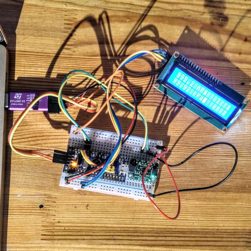
The finished project is a tangle of wires on a breadboard, and the error handling is minimal, but I definitely have a barometer with an LCD readout.
You can get the code in my lps25_pressure_sensor_demo github repo.
The eventual goal is to incorporate the LPS25 breakout board into a larger project I have on the go, but I thought it would be useful to learn to use it on its own - and pick up a few more bits of knowledge along the way. Therefore I built this standalone project. I wanted to:
- Use the LPS25 pressure sensor.
- Learn to use the HD44780 LCD panel.
- Learn how to share I2C devices on a bus with Rust.
- Be able to re-use the setup to test other sensors.
The larger project this is eventually intended for already contains an e-ink display, LEDs, a CO2 sensor etc. and is starting to become quite complicated.
By doing this in a more self-contained project, I could get to a complete state faster, focus more on exactly what I wanted to learn, and build something that was immediately useful (if one considers an atmospheric pressure reading useful).
I had a lot of fun building this over the holidays.
The components
The microcontroller
I elected to use one of the Blue Pill boards I have in my drawer of components. The Blue Pill is a very affordable STM32 (ARM Cortex M3 by STMicroelectronics) microcontroller board. It’s easy to use, powerful, and cheap enough it can be embedded in the project. The CPU runs at up to 72MHz, it’s got 20KiB of RAM and 64KiB of Flash space.
If I didn’t have these at hand, I might have gone with a Raspberry Pi Pico, or something else based on the RP2040.
The STM32 family of microcontrollers are very well supported in Rust, which is what I wrote this project in. I’ve been trying to get more comfortable in Rust for a while, and this felt like another good project to practice with.
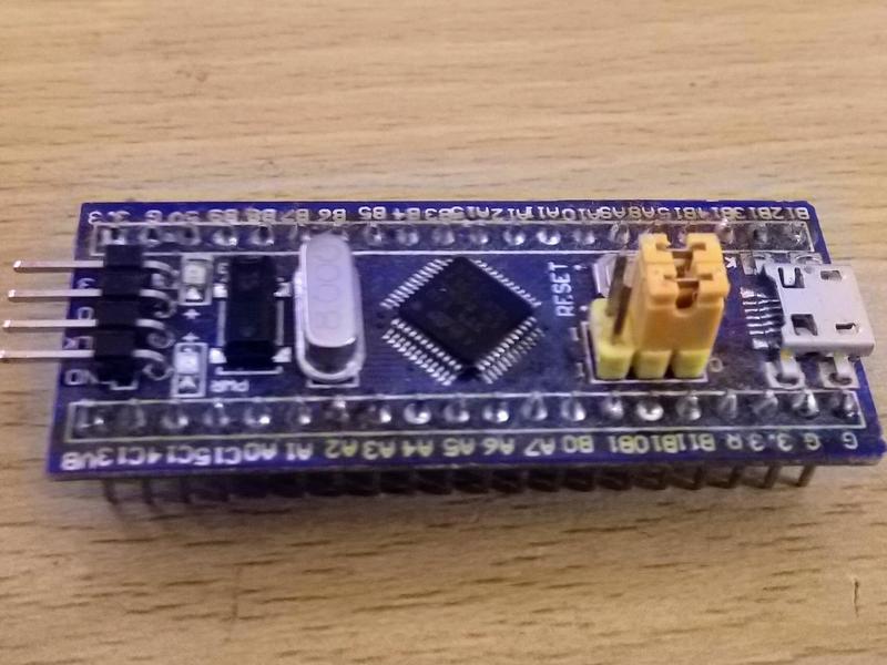
You can read more about the Blue Pill on STM32-base’s Blue Pill page.
The programmer/debugger
The Blue Pill does not contain an on-board programmer or debugger. In order to program it, you need an external programmer that talks ARM’s SWD protocol. I use a clone of the ST-Link V2 USB dongle. I’ve also used the ST-Link to provide power.
Previously I’d used OpenOCD to program the Blue Pill, but my recent experience following the Knurling-rs projects showcased a much more ergonomic workflow which I wanted instead. The Knurling projects use the nRF52840 DK board rather than the Blue Pill, but it is equally possible to use the same convenient tooling with the Blue Pill.
By using probe-rs and its probe-run component to flash
the program onto the microcontroller and to interact with it we can run
programs on the microcontroller with just cargo run, which is really nice! In
order for probe-rs to work, one must make sure the ST-Link V2 debugger runs
the latest firmware, which I did with the
STSW-LINK007
firmware upgrade application. It is a Java app which works well on Linux.
I started the project with Levi Pearson’s blue_pill_base git repo for working in Rust with the Blue Pill. This sets up the probe-rs integration and more and gives a nice and easy way to start the project out without setting up all the boilerplate from scratch.
The sensor
It wouldn’t be much of a barometer without a pressure sensor. The one I have is Adafruit’s LPS25 breakout board. It contains ST’s LPS25H MEMS pressure sensor. It measures absolute ambient pressure between 260-1260 hPa and can be read over I2C.
The lps25hb crate is the Rust driver for this sensor.
The display
The display is another thing I already had in my parts drawer. However, it’s not a part I’d used yet.
It’s an LCD panel displaying 16 characters on each of 2 rows and is addressed over I2C. It has a Hitachi HD44780 LCD controller, and an I2C backpack already soldered on. The device is sold by Handsontec as the I2C Serial Interface 1602 LCD Module. There are many compatible devices like this, sold under different names.
The IC on the backpack is a PCF8574T - an NXP version of a TI port expander chip. This IC lets the backpack control the 16 pins on the LCD panel with just the four needed for I2C (counting power and ground).
It would be interesting to talk to the port expander on its own at some point, but as I use the hd44780-driver crate to control the screen there is no need as it already includes the ability to use the I2C backpack. The driver is easy to use and made displaying the sensor readings very easy. The tricky part was generating the text to display - more on that later.
Wiring up the components
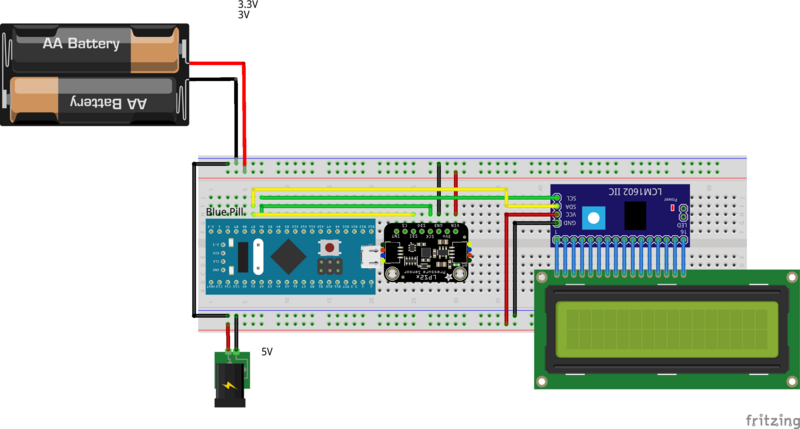
This diagram shows the microcontroller, sensor, display and how they’re connected.
The programmer
This wiring diagram doesn’t show the ST-Link programmer, instead it shows how power is hooked up in the barometer build.
To replicate this build, first you need to connect up your programmer/debugger to the Blue Pill (see connecting your debugger for a pin-out diagram). For more information on the exact programmer I have used - look at the “ST-LINK/V2 Clone” section.
The I2C devices
Both the pressure sensor and LCD panel communicate over the I2C bus. That bus is made up of two wires, a clock wire and a data wire. The only tricky thing is that the labels on the pins are different on all three devices.
There are two I2C devices on the Blue Pill - I’m using the first of those. The lines of that is made up of SCL1 and SDA1, which are labeled PB6 and PB7 on the PCB. You can see the pinout diagram and chart on microcontrollerslab.com’s Blue Pill pinout - peripherals programming features article.
Adafruit has an article on how to connect the LPS25 on the LPS25 pressure sensor pinouts page on adafruit.com.
For the clock signal, there should be a connection between:
- PB6 (SCL1) on the Blue Pill.
- SCK on the LPS25.
- SCL on the display.
For the I2C data line, there should be a connection between:
- PB7 (SDA1) on the Blue Pill.
- SDI on the LPS25.
- SDA on the display board.
Power
All three devices we’re using are capable of operating at 5V. The Blue Pill can take 5V via USB or the pins marked 5V. The LPS25 is a 3.3V chip, but the Adafruit breakout board includes a voltage regulator that takes between 3 and 5V and safely converts it down. The display will only work fully at 5V - it will partially work at 3.3V, but the displayed text won’t be backlit and will be hard to read.
So you can totally choose to power this entirely at 5V. I chose to feed the pressure sensor 3.3V as the ST Link has a handy 3.3V output in addition to 5V, so it was very simple to do.
Adjust the display
Note that the display backpack has a potentiometer for contrast on the back. If you don’t see any text displayed - try adjusting that potentiometer.
Code
Crates used
A lot of the crates I need were brought in with the base repo that I based my code on. But, I did need a few more. The crates used over those to get the Blue Pill working are:
- hd44780-driver - for the display.
- lps25hb - for the pressure sensor.
- shared-bus - to share the I2C bus.
- alloc-cortex-m - to format text.
I2C setup
Easily the most difficult part of this project is actually setting up the microcontroller peripherals, clocks and the I2C bus. Luckily much of that was also done for us in the base repo we cloned.
It’s a fair bit of voodoo. Here’s what it looks like:
// Get access to the core peripherals from the cortex-m crate
let cp = cortex_m::Peripherals::take().unwrap();
// Get access to the device specific peripherals from the peripheral access crate
let dp = pac::Peripherals::take().unwrap();

// Take ownership over the raw flash and rcc devices and convert them into the corresponding
// HAL structs
let mut flash = dp.FLASH.constrain();
let mut rcc = dp.RCC.constrain();

// Freeze the configuration of all the clocks in the system and store the frozen frequencies in
// `clocks`
let clocks = rcc.cfgr.freeze(&mut flash.acr);
let mut delay = delay::Delay::new(cp.SYST, clocks);

// Acquire the GPIOB peripheral
let mut gpiob = dp.GPIOB.split(&mut rcc.apb2);

// Set up I2C
let afio = dp.AFIO.constrain(&mut rcc.apb2);
let mut mapr = afio.mapr;
let mut apb = rcc.apb1;
let scl = gpiob.pb6.into_alternate_open_drain(&mut gpiob.crl);
let sda = gpiob.pb7.into_alternate_open_drain(&mut gpiob.crl);

let mode = i2c::Mode::Standard { frequency: 40.hz() };
let start_timeout_us: u32 = 10000;
let start_retries: u8 = 5;
let addr_timeout_us: u32 = 10000;
let data_timeout_us: u32 = 10000;

let i2c = i2c::BlockingI2c::i2c1(
    dp.I2C1,
    (scl, sda),
    &mut mapr,
    mode,
    clocks,
    &mut apb,
    start_timeout_us,
    start_retries,
    addr_timeout_us,
    data_timeout_us,
);
Shared bus
With rust’s ownership model, as soon as you pass the pins to the i2c1 device, and then the i2c device to the peripheral driver - you can no longer use those pins elsewhere. This is fundamental to how Rust operates, and how the HAL (Hardware Abstraction Layer) is designed.
Since I have both an I2C pressure sensor, and an I2C display, I need a way
to re-use the I2C pins, and share the bus. The shared-bus create does
exactly that. It manages the ownership and locking required, and lets me
give proxy objects to the drivers that need the I2C bus. Using it is very
simple - initialize it with the real I2C device, then acquire a proxy with
.acquire_i2c().
let i2c_bus = shared_bus::BusManagerSimple::new(i2c);
i2c_bus.acquire_i2c()  // proxy ready to use.
Pressure sensor
The lps25hb crate makes taking pressure readings very simple. First initialize it:
// configure I2C interface for the LPS25HB driver.
let i2c_interface = I2cInterface::init(i2c_bus.acquire_i2c(), I2cAddress::SA0_VCC);
// create a new LPS25 instance with the I2C interface
let mut lps25hb = LPS25HB::new(i2c_interface);

lps25hb.sensor_on(true).unwrap();
// enable Block Data Update
lps25hb.bdu_enable(true).unwrap();
lps25hb.set_datarate(ODR::_1Hz).unwrap();
Then take a reading:
let press = lps25hb.read_pressure().unwrap();
You can also take a temperature reading with the sensor:
let temp = lps25hb.read_temperature().unwrap();
However, you can’t rely on that temperature reading. Right now, it’s 7C below what I expect to see when I read it. I think it’s just intended for coarse grained adjustments internal to the sensor itself. In fact, the data sheet doesn’t mention the temperature sensor as a feature.
LCD panel
The hd44780-driver crate is also very easy to use. First initialize the driver and device and set up some defaults for the display:
let mut lcd = HD44780::new_i2c(i2c_bus.acquire_i2c(), LCD_I2C_ADDRESS, &mut delay).unwrap();
lcd.reset(&mut delay).unwrap();
lcd.clear(&mut delay).unwrap();
lcd.set_display_mode(
    DisplayMode {
        display: Display::On,
        cursor_visibility: Cursor::Visible,
        cursor_blink: CursorBlink::On,
    },
    &mut delay
).unwrap();
Then writing to it is very easy:
lcd.write_str("First line", &mut delay).unwrap();
lcd.set_cursor_pos(40, &mut delay).unwrap();  // Move to 2nd row.
lcd.write_str("Second line", &mut delay).unwrap();
However, there is a wrinkle here. Formatting the string we’d like to write so
that we can insert the pressure reading would usually be done with the
format!() macro, but it’s not available!
In order to get it, we will need the alloc feature available, which we can
get by adding the alloc-cortex-m
crate. It needs a fair bit of setup though.
First we need to turn a feature on:
#![feature(alloc_error_handler)]
Import the required bits:
use core::alloc::Layout;
extern crate alloc;
use alloc_cortex_m::CortexMHeap;
Define the global allocator, and the alloc_error_handler.
#[global_allocator]
static ALLOCATOR: CortexMHeap = CortexMHeap::empty();

#[alloc_error_handler]
fn oom(_: Layout) -> ! {
    loop {}
}
Then at the start of the program set up the heap:
let start = cortex_m_rt::heap_start() as usize;
let size = 256; // in bytes
unsafe { ALLOCATOR.init(start, size) }
Finally, we have alloc support, and we can use the format! macro like
we normally would:
let hpa_str = alloc::format!("{:.1} hPa", press);
Our writing to the LCD panel therefore actually looks like:
let hpa_str = alloc::format!("{:.1} hPa", press);
lcd.write_str(&hpa_str, &mut delay).unwrap();
The main loop
The code spends its time reading from the pressure sensor, writing to the LCD panel, then pausing for a while. A slightly shortened version looks like:
loop {
    let press = lps25hb.read_pressure().unwrap();
    let hpa_str = alloc::format!("{:.1} hPa", press);

    lcd.clear(&mut delay).unwrap();
    lcd.write_str(&hpa_str, &mut delay).unwrap();

    delay.delay_ms(2_000_u16);
}
You can read the code in my lps25_pressure_sensor_demo repo.
Running the code
The probe-rs tooling makes this so simple - there’s no need to start a
separate debugger or anything. Just run it with:
cargo run --bin lps25_barometer --release
That flashes the code onto the device and returns logging to the console. It also shows you tracebacks if your code crashes or is aborted. It’s almost easy to forget the code is running on a separate device.
Summary
The crates to interact with the sensor and display are very simple to use, and
using Rust for embedded programming has been a joy - especially with the
probe-rs tooling. I will definitely carry on using Rust when writing embedded
software like this.
There are some parts that are still a little arcane, like the hardware setup and finding out how to get formatting support, but nothing a little time with Google couldn’t solve.
I look forward to incorporating what I’ve learned here in my larger air quality sensor project, and to try out a few more I2C sensors.